Table of Contents
- Introduction
- Ground Comm Power
- Propeller Alpha/Beta/Reverse
- Smooth Braking
- Proline Radios
- EHSI PRE/ACT/XFR Function
- Gen Ties Switch
- Engine Anti-Ice
- Pressurization
- Auto-Ignition
- Rudder Boost
- Condition Lever Settings
- Overhead Panel
- ITT/Torque Limits
- EHSI Modes
- Fuel Panel
- Pilot’s Left Subpanel Switches
- Pilot’s Right Subpanel Switches
- Pilot’s Main Panel
- Audio Control Panel
- Environmental Control Panel
-
Experimental Flight Model
Introduction
This mod continues the work started by @uncertifiedpilot with the original JongePionier mod. Our intention is to delve deeper into systems, flight model and engine performance in order to create the most faithful reproduction possible of the original C90B, within what X-Plane permits.
Your “Operating Manual” for this mod is the actual POH. Alas, this is copyrighted material and we cannot freely distribute it, but they are available for sale online. Save having a copy of the POH, your “best friend” is our published checklist, which is 99% off the POH with minor (negligible) differences to allow for simulation limitations and some of the idiosyncrasies of flying online. Fly the checklist and you will have as true-to-life experience as you can have other than sitting at the left seat of an actual C90B.
If you exceed limits or decide not to follow procedures there are failures waiting for you right around your simulated corner. Fuel consumption, engine performance and endurance, electrical systems, navigation and avionics are all faithful to POH.
This document seeks to explain in some detail the major parts of this mod and how they differ from the stock LR C90B and the original JongePionier. It is not meant as a replacement for the POH, but rather as a guide for you to understand the systems in question.
We sincerely hope that you will enjoy flying this plane as much as we have enjoyed making it.
The JP_Evo team: @pilotmarcog, @IBAV8N, @jeffory, @FSPilot_CZ, @avnav
Ground Comm Power
The Ground Comm Power button is a square push button located in the middle of the center main panel, between the Paging and Interphone volume knobs and above the altitude preselector. As in the real airplane, it routes power to the COM1 radio. It is used for operating that radio without using too much of the airplane’s battery, e.g. for obtaining clearance from ATC prior to starting engines.
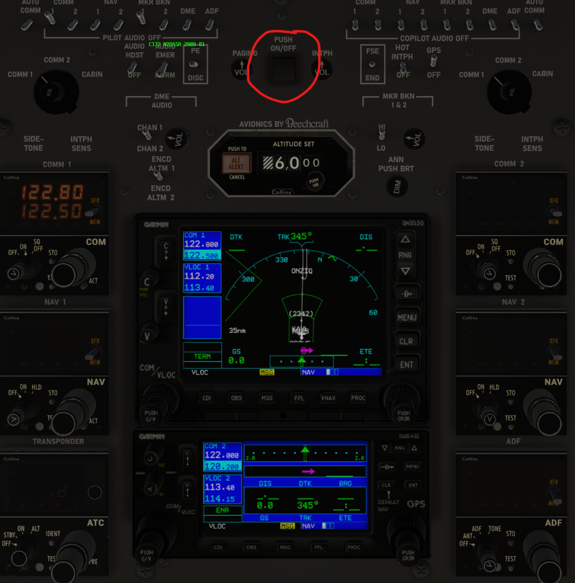
To activate, press once to depress the button (it will stay depressed provided neither the battery switch nor external power are switched to ON). To deactivate it press again (the button will pop out), or turn on the battery switch or external power.
Note that the COM1 radio’s mode selector must be in the ON position to transmit or receive.
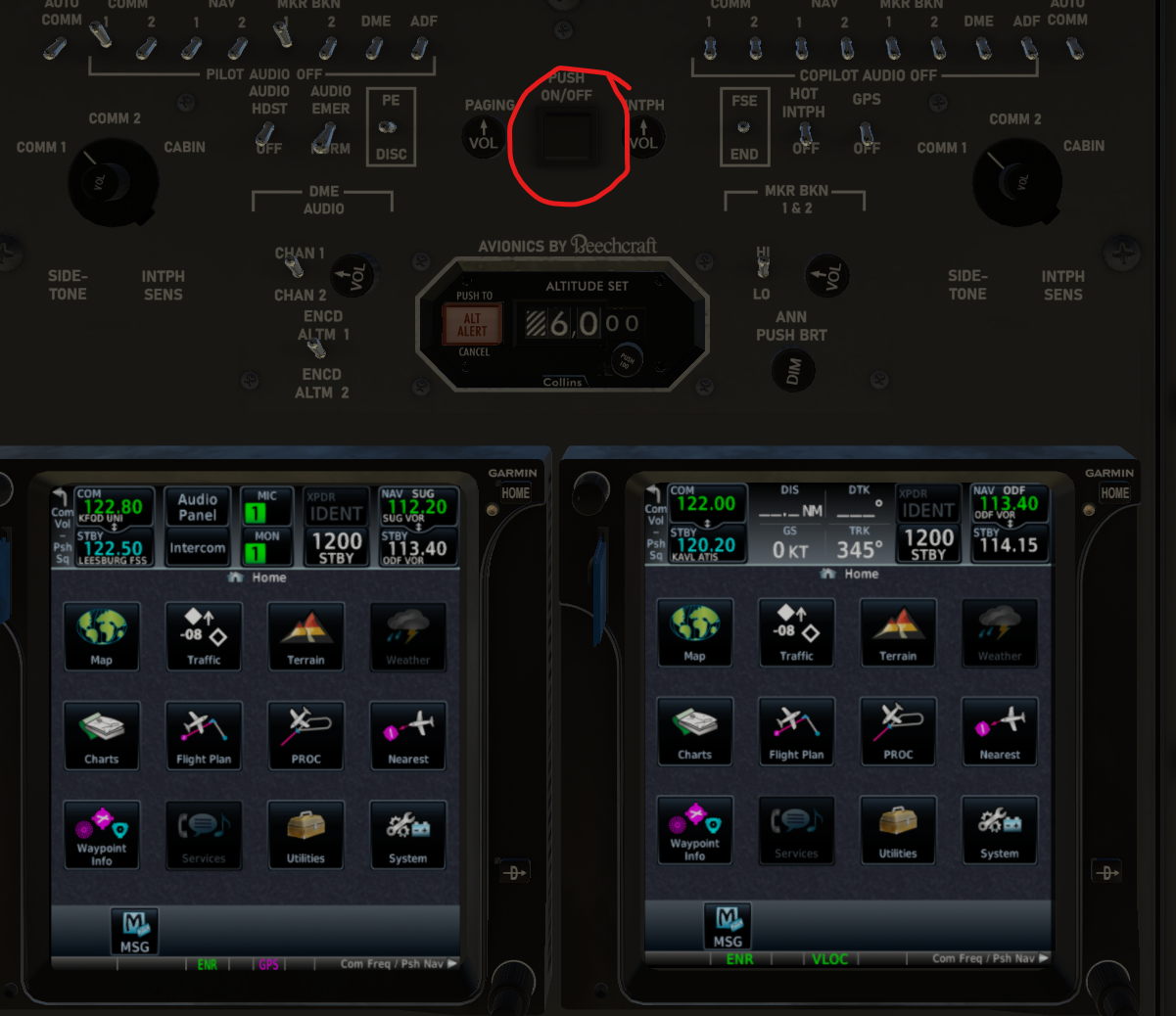
In the case of the GTN version, both GTN units will automatically power on as soon as you click the Ground Comm switch.
Propeller Alpha/Beta/Reverse
A new command was added “laminar/c90/powerplant/beta” to replace the default beta toggle. In order to activate the new command you need to map it either to a keyboard key (we suggest “/”) or a joystick or throttle quadrant button.
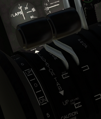
Alpha Mode
The forward-most detent of the throttle gate sets positive propeller pitch. Your hardware throttle will need to be fully retarded to enter this mode from the beta mode. Use this mode for takeoff and any time the aircraft is airborne.
Beta Mode
Beta mode flattens the propeller pitch so that the propeller is no longer making thrust. This helps control taxi speed without using the brakes. The center detent sets flat propeller pitch and has no effect on engine output. Advance your hardware throttle to produce an aggregate negative pitch which will slow the plane, and retard the throttle to allow the plane to slowly accelerate. Use this mode in combination with brakes for realistic ground handling.
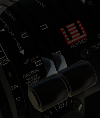
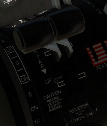
Reverse Mode
Reverse causes the propeller blades to twist so that they are making reversed thrust. After touch-down use reverse mode to quickly slow the plane after landing. The rate of deceleration is determined by engine output in this mode, so apply throttle as necessary and keep an eye on the ITT/Torque gauges.
A toggle below 50 KIAS while in reverse mode will automatically activate beta mode. Never use reverse below 40 kts as it can cause stones to be lifted up off the surface that can damage the engines and propellers.
Smoother Braking
If you are not using toe brakes, assign the command “laminar/c90/brakes/smooth” to your preferred braking control in your C90 EVO control profile. It builds braking force gradually and is not jerky like the Laminar command option.
Proline Radios
Memory function instructions
Each COM radio is equipped with 6 memory registers. NAV/ADF radios are equipped with 4 memory registers. To use the memory function follow the following instructions:
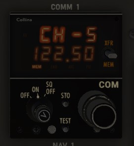
- The XFR/MEM switch is used to:
- Transfer the Standby frequency to the Active (Up Direction)
- Display next memory register (Down Direction)
- Toggle the XFR/MEM switch down to view the first memory register. The active frequency display will now show “CH-1” and the standby frequency display will show the contents of the memory register. If no frequency had been previously stored, the previous standby frequency will be displayed.
- Use the knobs to select the desired frequency to be stored. You will see the standby display show the frequency you have selected.
- Once you have selected the desired frequency press (click) the STO button twice. The MEM display will light up for 1 second and the frequency will be stored in memory. The memory will automatically advance to the next register.
- You continue to toggle the XFER/MEM switch to show CH-2 through CH-6 (or CH-4 in the case of NAV/ADF) and one more time to exit MEM mode and display the active frequency.
- To activate a stored frequency toggle XFR/MEM down to select the desired channel and toggle up to transfer to Active.
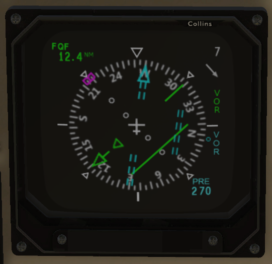
EHSI PRE/ACT/XFR Function
The C90 EVO offers a faithful simulation of the Collins EFIS-84 Electronic Flight Instrument System. A very useful, if less than intuitive feature of this system allows the flight crew to preselect and store course settings upcoming in the flight plan.
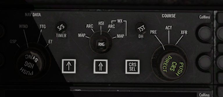
Essentially, the DSP (above) allows setting heading, course, selecting nav data, HSI mode and whether to display bearing pointers in addition to the PRE/ACT/XFR function.
Since the DSP is not visible when looking at the panel, we strongly recommend assigning the following commands in your C90 EVO control profile:
| Function | Command |
|---|---|
| Autopilot heading up | sim/autopilot/heading_up |
| Autopilot heading down | sim/autopilot/heading_down |
| Autopilot heading sync | sim/autopilot/heading_sync |
| OBS HSI up | sim/radios/obs_HSI_up |
| OBS HSI down | sim/radios/obs_HSI_down |
| Avionics Course Sync Selector Switch | laminar/c90/avionics/switch/crs_sync_sel |
| Avionics Course Selector Switch | laminar/c90/avionics/switch/crs_sel |
| Avionics Course Sensor Selector Dial Up | laminar/c90/avionics/dial/crs_sensor_sel_up |
| Avionics Course Sensor Selector Dial Down | laminar/c90/avionics/dial/crs_sensor_sel_dn |
| Avionics Decision height Dial Up | laminar/c90/avionics/dial/decision_height_up |
| Avionics Decision height Dial Down | laminar/c90/avionics/dial/decision_height_dn |
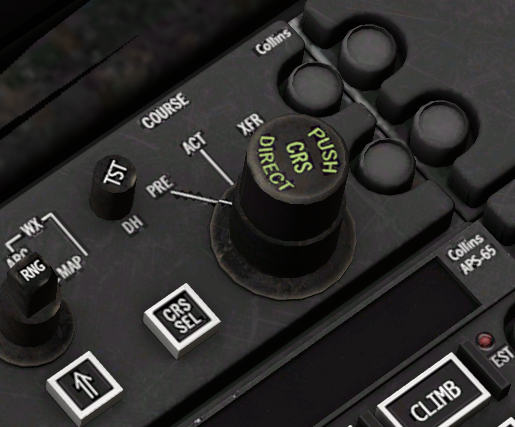
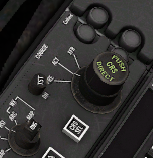
Now that we’ve assigned our commands, let’s start by learning what the Course Selector button (CRS SEL) does. Assuming your plane is up and running, press and hold CRS SEL until a white box appears in the EHSI display:
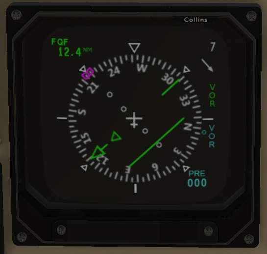
If we tap CRS SEL we can cycle through our available nav sources. Be aware that GPS must be powered and the NAV1 radio must be tuned to an active frequency to be considered available. If you tune NAV1 to an active localizer/ILS frequency you will notice that LOC will replace VOR in the selection box.
When we have determined our desired nav source, we again press and hold CRS SEL for a few seconds to select the source. We know we have made our selection when the white selection box disappears. Note that if you do not press and hold CRS SEL upon choosing your source the selection box will time out and no change to your nav source will be made.
Next let’s set the our COURSE knob to PRE:
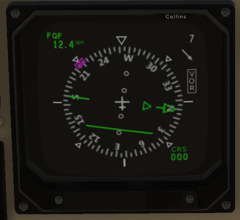
And we’ll see that the EHSI is now displaying PRE instead of CRS in the lower right:
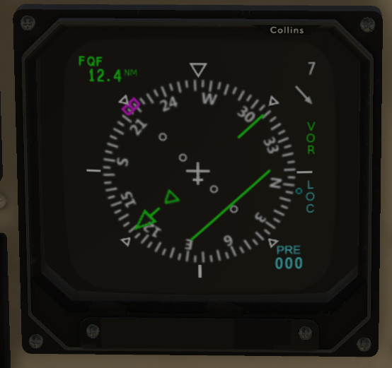
Also notice that another ‘source’ has appeared below our selected nav source. In this case we can tap our CRS SEL button to toggle between VOR and LOC. If we adjust our course using one of either of the two commands above that we wisely added to our C90 EVO control profile, we see a secondary blue CDI arrow appear:
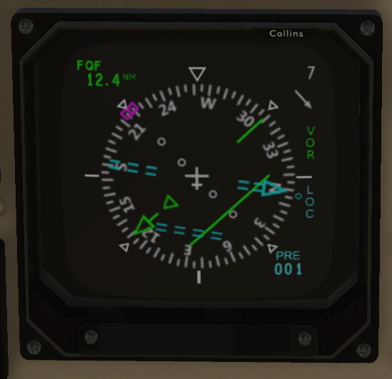
We can now preselect a course for later use, e.g. an ILS course. Next let’s tap CRS SEL once again:
We can preselect a completely different course for VOR:
Set the COURSE knob to ACT:
And we see that the CRS is back in the lower right corner of the EHSI. Now we can control our active course again.
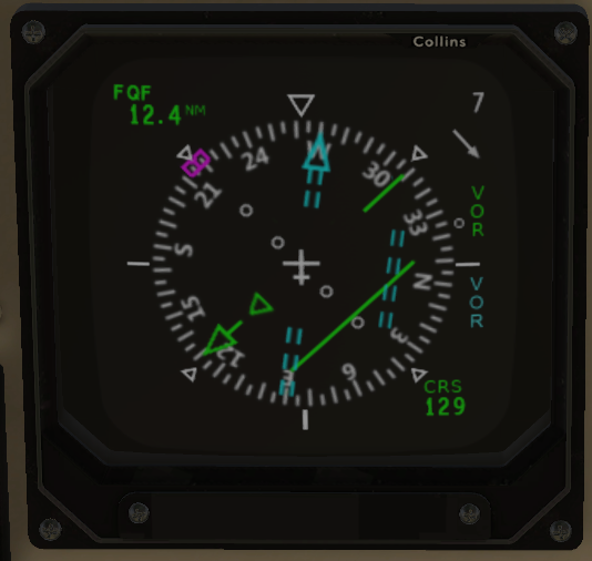
If we would like to transfer a preselected course to our current course, we will rotate our COURSE outer knob to XFR:

The knob will spring back to ACT when release it, and our active course will now be what we preselected:
The XFR function will return either the LOC or VOR preselected course depending on what NAV1 is tuned to. If NAV1 is tuned to an LOC/ILS frequency, for example, XFR will transfer the preselected LOC course. Likewise, VOR will be transferred if NAV1 is set to a VOR frequency. If we made a mistake or for whatever reason need our previous course again, simply turn the knob to XFR again.
Bus Tie Switch
A three-position generator bus tie switch is located in the pilot’s subpanel.
- The OPEN position causes both the left and right bus tie relays to open and isolate the generator buses from the center bus.
- The NORM position allows the automatic closure of the left and right bus tie relays when either generator or the external power comes on. If the battery is the only source on line, both generator bus tie relays open to isolate the left and right generator bus loads from the battery. Normal and Max Electric Heat and Air Conditioner are also disabled. Equipment which remains operational is identified with a white circle around the control switch.
- Momentarily selecting the MAN CLOSE position during battery operation closes both generator bus ties to power the generator buses from the battery.
The battery bus tie connects the battery to the center bus. The battery switch closes the battery bus tie when in the ON position. This makes the battery available for center bus loads or for recharging.
Engine Anti-Ice
These switches control vanes that are positioned in the engine air inlet ducts that prevent ice and foreign objects from entering the engines when the anti-ice is ON, but at the loss of some power.
The PT-6 engine is unusual in that the air enters the engine from the rear and travels through the engine toward the front. The exhaust is actually near the front of the engine. The reason for doing this is so there can be two completely separate turbines and shafts, one for driving the propeller which is called the power turbine, and the other for driving the compressor and generating the hot gasses used to spin the turbines, called the gas generator turbine.
Air enters the inlet just under the propeller, travels in a duct straight back until it is about even with the back of the engine, and starting there the duct curves up to the rear of the engine where it enters the compressor. The air goes forward through the compressor, then combustor section where it is mixed with fuel and burned, then the hot gas drives a turbine (that in turn drives the compressor). The gasses then drive a second turbine, which drives a shaft connected to a gear box that drives the propeller, and from there the hot gasses go out of the exhausts. It is actually possible to start this engine without the propeller even moving if the propeller is held stationary since the gas generator turbine, shaft, and compressor are not physically connected to the power turbine and propeller drive.
The engine ice vanes inside the duct can be positioned in such a way that the air is forced to make a much sharper turn in the intake duct before reaching the engine. Objects with more mass than air molecules, such as ice or stones, can’t make that turn and are instead diverted to an outlet on the bottom of the nacelle. Forcing the air to make that severe turn reduces some of its velocity in the duct as it is getting to the engine and results in the engine not being able to produce quite as much power.
The Engine Anti-ice switches should always be ON for ground operations and for takeoff on grass, dirt, gravel or snow and ice covered runways. For a smooth, clean pavement takeoff without icing conditions, the anti-ice should be turned OFF just before taxiing onto the runway and left off in flight unless needed. It is always turned on before entering possible icing conditions in flight (visible moisture and temperatures at or below 5 degrees Celsius).
After landing, the anti-ice is turned back ON immediately after taxiing off the runway to help prevent damage from any small stones or other objects that might be ingested while taxiing. The anti-ice can be on for landing if the runway potentially has debris of any type on it. The anti-ice switches are left ON when the engines are shut down, and should be ON before starting the engines for the next flight.
In order to simulate this system we have introduced a random probability of failure due to FOD ingestion any time the aircraft is on the ground and the vanes are closed. The probability of failure from FOD ingestion is significantly higher when the airplane is over rough surfaces as compared to smooth (paved taxiways and runways) surfaces. A useful rule of thumb is to turn on anti-ice anytime you’re on the ground unless you need takeoff power.
Upon closing the vanes you should pick up about 100 ft-lb of torque, so please be mindful not to exceed engine torque limitations or you could invite another type of failure.
Pressurization
Pressurization comes from bleed air, air that is bled from the engine compressor, that is brought into the cabin raising the cabin pressure. That pressure is controlled by an outflow valve in the rear pressure bulkhead behind the rear of the cabin. The outflow valve controls how much air is allowed to escape which maintains the cabin pressure, and is in turn controlled by the Pressurization Controller on the center console. For pressurization to work, the Bleed Air Switches on the copilot’s subpanel must be on (they should be on for engine start anyway). To set the pressure controller, you’ll note that on the rotating dial there are two sets of numbers in an inner and outer ring. The inside numbers are outside altitude, and outer ring of numbers are for cabin altitude. Generally this dial is set prior to starting engines. To set it, at the lower right side of the dial is the CABIN ALT knob that you twist to turn the dial. Which numbers you use is determined by your planned cruising altitude and your destination’s field elevation. As an example, say you’re planning a flight from an airport at near sea level field elevation to an airport at 3,000 feet field elevation. It’s a short flight so you’re planning to cruise at 12,000 feet. Looking at the dial, you’ll see that on the outside ring of numbers 3,000 feet corresponds with a 16,000 feet outside altitude. But no matter, we set the dial to the destination field elevation plus 500 feet so that 3,500 feet is under the pointer at the top. We always want to set the controller to 500 to 1,000 feet above what we actually plan to use so the system doesn’t “hunt” (add pressure, then lose pressure, then add pressure, etc.) for the proper pressure, which would be very uncomfortable for you and your passengers. We never want to allow the outside pressure to be higher than the interior pressure as the fuselage structure is not built to handle that. There is a valve that will open if the exterior pressure starts to be higher than the interior but it is not controlled and will result in a very sudden change in the interior pressure which is not comfortable for passenger’s ears. We also want to be sure the cabin is fully depressurized before landing because if it isn’t, the pressure will suddenly release as soon as there is weight on the wheels (switches on the main gear struts control that), and that also can be very uncomfortable to you and your passengers.
Now imagine we’re planning a longer flight from an airport with a field elevation of 1,500 feet, going to an airport that’s at 900 feet elevation, and we’re planning to cruise at 22,000 feet. Before we start the engines, we’ll set the dial so the inner ring’s 22,500 to 23,000 feet indication is under the pointer at the top. That will let the cabin pressure drop during our climb but only until it reaches a pressure equivalent to 7,750 to 8,000 feet altitude (the number on the outer ring under the pointer). During the climb we’ll check the cabin climb rate indicator just in front of the power levers to make sure the cabin is climbing at only 500 feet per minute (even with the airplane actually climbing at 1,500 feet per minute or more) so we don’t cause discomfort to our passengers’ ears. The rate controller is a knob to the lower left of the dial. We’ll check the cabin climb indicator and cabin altimeter next to it every few thousand feet as we climb to verify everything is working properly. We also check it every so often while we’re cruising to verify the pressurization is still working properly, making sure the selected cabin pressure matches what the cabin altimeter is reading. If during the flight, ATC has us climb to a higher altitude than we planned, we’ll set the controller dial to the new altitude plus 500 to 1,000 feet. Same thing if we’re told to descend, we set the controller to the new assigned altitude plus 500 to 1,000 feet. When we’re nearing our destination, we go through the descent checklist which includes setting the pressure controller to the destination field elevation, 900 feet in this scenario, plus 500 feet. So, in this scenario we’ll turn the CABIN ALT knob to set the dial outer ring numbers to 1,400 feet just before we start descending. The cabin pressure will probably increase a bit until it’s at the maximum differential between the outside and inside pressures, and that’s normal.
Auto-Ignition
These switches turn on the engine ignitors (basically really large, expensive spark plugs) any time the torque is below 400 ft-lbs. This is useful if the engine flames out due to heavy rain ingestion or for any other reason, as it will almost immediately re-light the engine. These switches should always be OFF for ground operations as otherwise the ignitors will be continually sparking while you taxi and the ignitor plugs will quickly wear out and need to be changed prematurely.
In flight, torque should usually never drop below 400 ft-lbs and so these switches are turned ON just as the airplane is about to enter the runway for takeoff, and are left on during the entire flight until after landing and the airplane has exited the runway. The time during the landing flare and rollout where the torque is below 400 ft-lbs is minimal and so the switches can stay on during that time. When you are clear of the runway after landing, run the after landing checklist which includes turning off the auto-ignition switches.
Rudder Boost
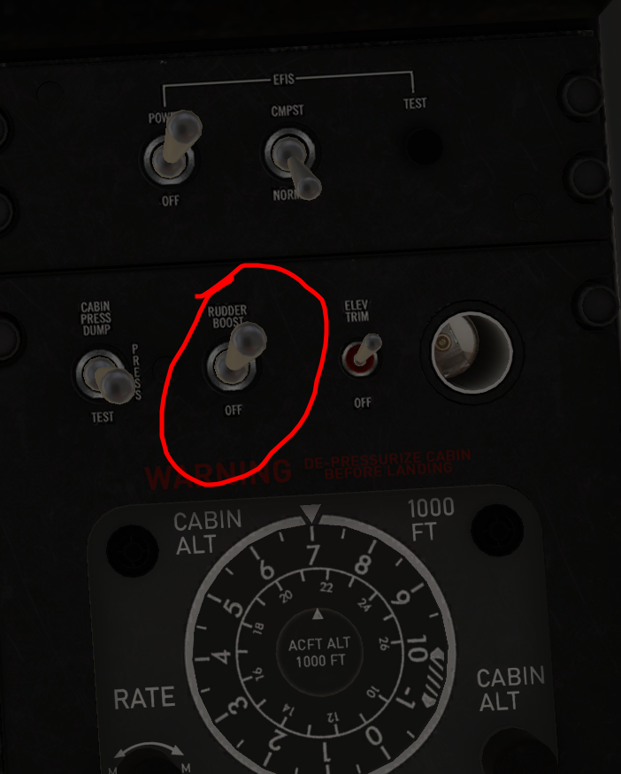
In the case of engine failure, the rudder boost system, when enabled, will help compensate for the consequent thrust asymmetry.
The system employs a pressure differential sensor in the pneumatic (bleed) manifold that compares the pressure produced by each of the engines. If the differential exceeds 50 psi, one of two servos connected to the rudder cables will actuate, left servo for a right engine bleed pressure reduction and vice-versa, moving the rudder pedals and deflecting the rudder surface to compensate for the thrust asymmetry.
This asymmetry can be substantial during takeoff and climb and the system will act quickly to reduce the likelihood of a wingtip stall and reduce the pedal effort required by the flight crew as rudder trim is applied. The rudder boost switch should be on before flight.
Condition Lever Settings
The condition levers in turbine engines control the amount of fuel delivered to the engine when the power levers are in the idle position. They are used mostly during engine startup, but under some circumstances you may be able to use them for taxiing. There are basically three positions:
- The CUTOFF position is when the lever is all the way in the rear most part of its travel. In this position there is no fuel delivered to the engine. If the condition lever is taken to the CUTOFF position with the engine on it will flame out.
- The LOW IDLE position is when the lever is in the mid point and this is the position used during engine ignition. It may also be used for taxi in certain circumstances.
- The FLIGHT IDLE or HIGH IDLE position is when the lever is at the top of its travel. This is used in normal operation from takeoff throughout the flight until after landing. After slowing to taxi speed, pulling the condition levers back to low idle helps with maintaining a safe taxi speed.
It is actually possible to do the entire flight with the condition levers in low idle. The only thing that will be affected is that the engines will take a few seconds longer to spool up when the propellers are reversed, increasing your stopping distance a bit.
High idle should be used on the ground if the ITTs start to climb due to excessive electrical loads on the generators. A hot day, high field elevation with the air conditioner on increases electrical loads on the generators that can cause N1 to drop, which reduces airflow through the engine raising the ITT.
Overhead Panel
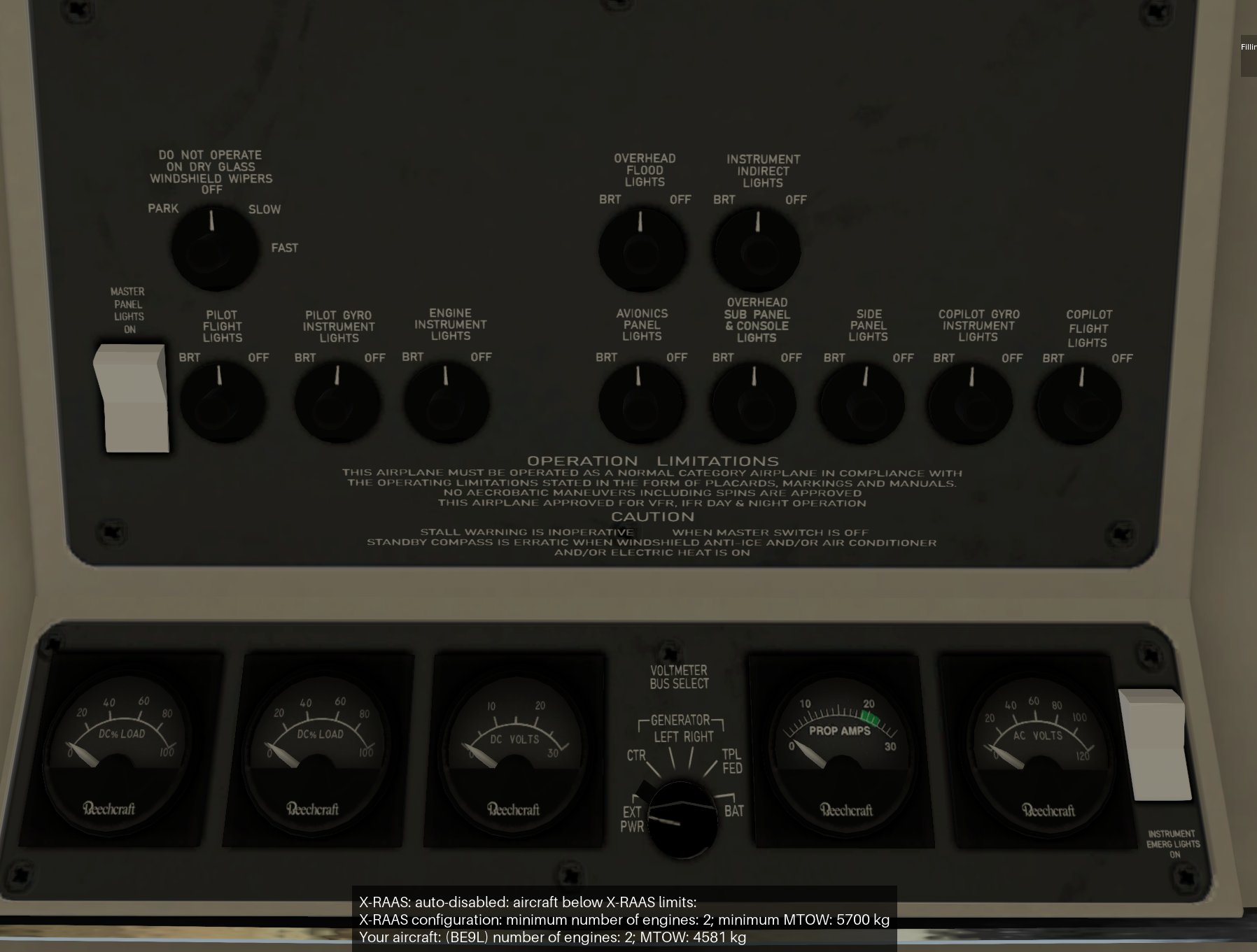
Emergency Light Switch
The Emergency Light Switch will provide instrument and panel lights at full intensity.
Voltmeter Bus Selector
At the center of the panel you can find the Voltmeter Bus Selector Switch which has 6 positions.
- EXT PWR - Voltmeter will indicate voltage provided by GPU if connected.
- CTR - Voltmeter will indicate voltage on Center Bus
- LEFT - Voltmeter will indicate voltage provided by Left Generator
- RIGHT - Voltmeter will indicate voltage provided by Right Generator
- TPL FED - Voltmeter will indicate voltage on Triple Feed Bus
- BAT - This position is Spring Loaded and will allow Voltmeter to indicate Battery Voltage
Master Light Switch
The Master Light Switch controls all lights in the cockpit and cabin. The Rheostat Knobs for each bank of lights will control their intensity. By default the plane will launch with all Rheostats at 50% intensity. You can manually adjust as desired the intensity of any of the banks.
AC Voltmeter
The rightmost gauge on the Overhead Panel measures AC Volts provided by the Inverter. It will only indicate after the Inverter (Either 1 or 2) has been turned on.
Windshield Wipers
The windshield wiper control knob now correctly rests in the center Off position. It has four positions
- PARK - This position is spring loaded and is meant to return the blades to the parked position if they should stop in the middle of their travel
- OFF - Wipers off and parked
- SLOW - Wipers on at the lowest speed
- FAST - Wipers on at the highest speed
ITT/Torque Limits
When setting our engine power levers, we need to keep an eye on our ITT and Torque gauges for each engine. Unlike piston engines, turboprop gas turbine generators can produce substantially more power than the gearbox and propeller mechanism can handle at low altitudes. If we remember that horsepower = (torque × RPM)/5252, we have an idea of how much horsepower is going into our propellers (e.g. 1315 ft-lbs @ 22000RPM = 550.84 horsepower, the maximum rated shp limit of our powerplant arrangement). For a given amount of power produced by the turbine, reducing propeller RPM will increase the torque on the propeller shaft. We need to be aware of that and provide some margin any time we reduce our propeller RPM, e.g. takeoff -> cruise climb -> cruise altitude.
Like a piston engine, our turbine’s power output will decline with altitude and higher air temperatures. For this reason, we will need to periodically advance our power levers towards 1315 ft-lbs to maintain climb performance.
At a certain point in our climb, however, we will notice that as we advance our power levers, keeping them just under 1315 ft-lbs, our ITT gauge is nearing red line. The ITT, or Inter-stage Turbine Temperature, is the temperature of the gasses between the high and low pressure portions of our engine. It represents the upper temperature limit that our gas turbine can tolerate, and it must be obeyed.
Our PT6A-21s are engineered to operate at an ITT of 695°C or below indefinitely. They can tolerate up to roughly 1100°C for a very short period of time during startup as engine-cooling airflow increases with turbine speed.
Rules of thumb: On takeoff we move our power levers slowly to keep ITT under red line and pay special attention to our torque gauges as we rotate and climb. Any time we anticipate reducing propeller RPM we need to make sure we have some torque margin beforehand. Above 14,000 - 20,000 ft altitude, depending on ISA, ITT will become our limiting metric. Once we have reached maximum 695°C ITT and torque begins to decline, we still need to keep an eye on ITT and reduce power accordingly as ITT will rise very slightly until we reach our cruise altitude. Typical cruise power settings are 200-250 pph per engine fuel flow or what the ITT/Torque will allow. Set power will increase as we descend.
EHSI Modes
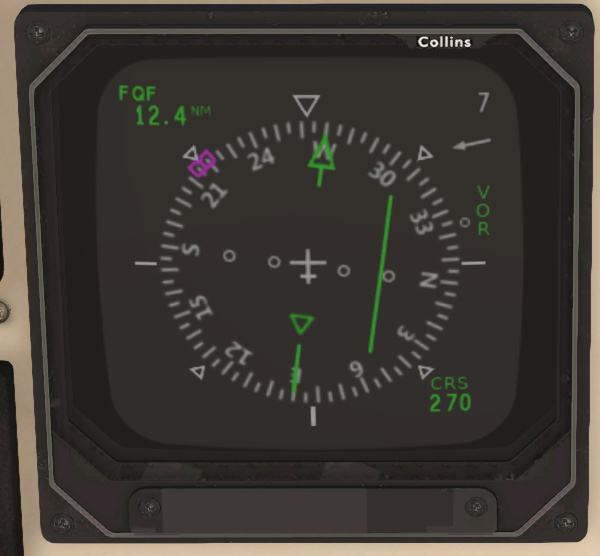
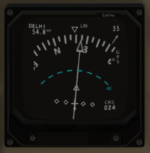
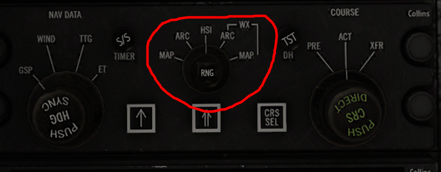 The Display Select Panel’s EHSI format switch allows us five different formats.
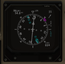
HSI - Displays a conventional HSI with no radar data.
ARC - This will display the upper 60° of the compass.
MAP - Map mode is not fully developed in the C90B EVO at the time of this writing.
HSI Mode
ARC Mode
ARC Weather Mode
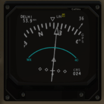
WX - Radar data is added to the display. A small yellow box surrounding a ‘T’ just right of the top center informs us that our radar system is emitting radiation. Also notice that the range arc is solid and not dotted.
Note: the master caution annunciator will flash to inform you that radar is enabled when not airborne, as it’s bad manners to irradiate ground personnel.
Bind the commands ‘sim/instruments/map_zoom_in’ and ‘sim/instruments/map_zoom_out’ in your C90B EVO control profile to adjust radar range.
Fuel Panel
The fuel system in the C90B consists of five fuel tanks in each wing plus several electric pumps pumps and valves. There are three tanks in the wing outboard of the engine nacelle (88 gallons total), the center wing tank in the wing between the nacelle and the fuselage (44 gallons), and a 61 gallon tank inside the nacelle behind the engine. 192 gallons of the total is useable, and one gallon is unusable as it would be trapped in a part of the fuel system where the fuel pickups can’t reach it.
The three tanks outboard of the nacelle are connected to each other with pipes and drain (gravity feed) through a pipe to the center wing tank. There are no valves or pumps involved with this. The inboard wing tank will gravity feed all but 28 gallons to the nacelle tank in the event of a pump failure, but ordinarily the fuel is pumped into the nacelle tank with the electric transfer pump. There is a check valve to prevent the nacelle tank from draining back into the center wing tank through that pipe when the pump is off. The nacelle tank also has an overflow drain pipe to the center wing tank, so if the transfer pump tries to overfill the nacelle tank the excess will just go back into the center wing tank.
Electric boost pumps are used to provide 30 psi head pressure to the engine-driven high pressure fuel pumps so that the engine driven fuel pumps don’t cavitate while pulling fuel from the nacelle tanks. The boost pumps should always be on any time the engine N1 is above 10 percent. If a boost pump fails, the engine driven fuel pump will be sufficient by itself to keep the engine running. However, operating the engine without the boost pump pressure is allowed for only 10 hours total time, after which the engine driven fuel pumps must be removed and overhauled or replaced because of accumulated damage from cavitation.
A crossfeed system is used to feed both engines from one wing in the event of a boost pump failure, so that the operable boost pump is supplying head pressure to both engine driven fuel pumps. Obviously this will soon result in a fuel imbalance between the wings and use up the fuel in the one wing twice as fast, so a landing should be made as soon as practicable or the decision made to fly without the crossfeed on. The time flown on that engine without boost pump pressure must then be recorded. Fuel can not be transferred from one wing to the other. Takeoffs with an inoperative boost pump are prohibited.
Here is a description of each switch on the fuel panel and what it does:
Transfer Pump
Transfers fuel from the center wing tank to the nacelle tank. This switch has three positions: OFF which means that fuel in the center fuel tank will not be pumped into the nacelle tank; AUTO in which the pump cycles on and off using a float switch in the nacelle to keep the tank within ten gallons of being full; and OVERRIDE which is used in the event of a float switch failure to make the transfer pump run continuously. When the center wing tank is empty, the pump will shut itself off and the L or R NO FUEL XFER annunciator light will illuminate. If you have fuel remaining in the center fuel tank and neglect to switch on the transfer pump, you will face fuel starvation if the nacelle tank runs dry. Rule of thumb, turn on the transfer pumps if fuel quantity total is greater than the nacelle quantity. The annunciators will let you know when it is no longer necessary to run the pumps.
Transfer Test
Moving this spring-loaded switch to the left (toward the rear of the airplane) will momentarily illuminate the L NO FUEL XFER light and activate the flashing amber MASTER CAUTION light (Note: the MASTER CAUTION LIGHT does not flash on the original Laminar C90B). Release the switch and it will spring back to the middle OFF position. Moving the switch to the right will momentarily illuminate the R NO FUEL XFER annunciator and activate the MASTER CAUTION flashing light.
Boost Pump
Provides head pressure to the engine driven fuel pump and must be on anytime the engine N1 speed is above 10% except in an emergency. Takeoff is prohibited with an inoperative boost pump.
Fuel Quantity
This switch allows you to see the total fuel quantity or the nacelle tank quantity in pounds. Jet fuel weighs about 6.7 pound per gallon, so if the 61 gallon nacelle tank is full, each gauge should read about 409 pounds with the switch in the NACELLE position. If the nacelle fuel quantity drops much below 340 lbs with the TRANSFER switch in AUTO or OVERRIDE, suspect a bad transfer pump or float switch if there is still sufficient total fuel quantity. If all of the tanks are completely full, each gauge with the FUEL QUANTITY switch set to TOTAL should show 1293 lbs. Bear in mind that full fuel tanks will limit how many people or how much cargo the airplane can carry. The airplane weighs about 6,970 lbs empty and has a 10,100 lb maximum takeoff weight and 9,600 lb maximum landing weight, so generally it is very rare to operate the airplane with full fuel. With full fuel you’d be limited to only 544 lbs for crew, passengers and baggage.
Crossfeed
Opens a valve in the event of a boost pump failure so that the fuel from the other wing and the boost pump on that side will feed both engines. When the valve opens, the CROSSFEED annunciator light will illuminate, and the flashing MASTER CAUTION will illuminate. AUTO makes the valve open when a fuel pressure sensor detects a boost pump failure. OPEN opens the crossfeed valve in the event that the pressure sensor fails. OFF closes the crossfeed valve and resets the CROSSFEED annunciator light to off.
Firewall Shutoff Valve
Under the fuel panel are the firewall shutoff valve switches under red guards. Those switches shut off all fuel to their respective engines, and are to be used in the event of an engine fire or to prevent a fire during a crash landing or similar situation. Open the guard, flip the switch down to OFF to close the valve. Closing the guard automatically moves the switch back to the OPEN position.
Pilot’s Left Subpanel Switches
EXT PWR
Used for applying external power from a battery cart or external generator if the aircraft battery is deemed not sufficient for starting the engines or if the airplane needs to be powered electrically for an extended time for maintenance or any other reason. In normal operations external power is not necessary and the switch should be set to OFF-RESET.
MIC
NORMAL is for use with a headset or hand microphone. The OXYGEN MASK position switches the live microphone circuit to the mic built into the oxygen mask stowed behind and above the pilot’s seat.
AVIONICS MASTER PWR
Controls power to the radios and navigation systems. It should always be OFF during engine start, or when the battery is on but radios and navs are not needed. Generally the radios and navs have their own built-in ON-OFF switches, and those switches are simply left on all the time. The avionics master switch is used instead to turn the radios on or off all together at once.
INVERTER
An inverter changes direct current (DC) electricity into Alternating Current (AC). The C90B uses AC in the torque gauge and some avionics. The inverter uses a lot of current and so usage should be limited as much as possible to being on only when the engines are running and the generators are on line so as not to run the battery down. The inverters on the C90B must be off (switch center position) for engine start. Earlier versions of the King Air C90 required the inverter to be on during start to power some of the earlier design engine gauges, but that raised the risk of an engine hot start especially if the battery was a bit weak.
The airplane is equipped with two inverters for redundancy. Generally the inverter that is used on each flight is alternated, so on one flight you’ll use #1, and on the next flight you’ll use #2, next flight #1 etc. That way if one malfunctions you’ll find about it and can have maintenance repair it so it will be available when you really need it.
ENG AUTO IGNITION
These switches turn on the engine ignitors (basically really large, expensive spark plugs) any time the torque is below 400 ft-lbs. This is useful if the engine flames out due to heavy rain ingestion or for any other reason, as it will almost immediately re-light the engine. These switches should always be OFF for ground operations as otherwise the ignitors will be continually sparking while you taxi and the ignitor plugs will quickly wear out and need to be changed prematurely.
In flight, torque should normally never drop below 400 ft-lbs and so these switches are turned ON just as the airplane is about to enter the runway for takeoff, and are left on during the entire flight until after the airplane has landed and exited the runway.
BAT
Battery switch, ON is up, OFF down. Battery voltage can be checked on the overhead panel gauge even with the battery switch OFF.
GEN 1 and GEN 2
Generator control switches. The C90B uses what is called a starter-generator in which the same unit functions as both a starter for starting the engine and a generator for producing DC electricity. It cannot do both at the same time, however, so these switches must be at the bottom OFF position for the engine starter to work properly. Once the engine is started and starter switches are OFF, the generator switch must be lifted to the top RESET position, held for at least one second, then released, whereupon a spring will move the switch to the middle ON position. The overhead gauges are then used to verify the generator load (how much current is being used from the generator) and the voltage being produced by the generator. If during the flight the generator drops offline for any reason, lift the switch to RESET again for at least one second and release it and hopefully the generator will come back to life.
If the generator switches are left on during the engine start, voltage is applied to the generator field windings, which will reduce the torque from the starter substantially. That could easily result in a hot start or hung start, potentially damaging the engines.
ENGINE ANTI-ICE
These switches control vanes that are positioned in the engine air inlet ducts that prevent ice and foreign objects from entering the engines when the anti-ice is ON, but at the loss of some power.
The PT-6 engine is unusual in that the air enters the engine from the rear and travels through the engine toward the front. The exhaust is actually near the front of the engine. The reason for doing this is so there can be two completely separate turbines and shafts, one for driving the propeller and the other for driving the compressor, called the gas generator turbine. So, air enters the inlet just under the propeller, travels in a duct straight back until it is even with the back of the engine, and starting there the duct curves up to the rear of the engine where it enters the compressor. The air goes through the compressor, then combustor section, then drives a turbine (that in turn drives the compressor). The gasses then drive a second turbine which drives a shaft connected to a gear box that drives the propeller. It is possible to start the engine without the propeller even moving if there is some way to hold the propeller stationary.
The engine ice vanes can be positioned in such a way that the air is forced to make a sharper turn in the intake duct before reaching the engine. Objects with more mass than air molecules, such as ice or stones, can’t make that turn and are instead diverted to an outlet on the bottom of the nacelle. Forcing the air to make that severe turn reduces some of its velocity in the duct as it is getting to the engine and results in the engine not being able to produce quite as much power.
The Engine Anti-ice switches should be ON for ground operations, and for takeoff on grass, dirt, gravel or snow and ice covered runways. For a smooth, clean pavement takeoff without icing conditions, the anti-ice should be turned OFF just before taxiing onto the runway and left off unless needed in flight. It is always turned on before entering possible icing conditions in flight (visible moisture and temperatures at or below 5 degrees Celsius).
After landing, the engine anti-ice is turned back ON immediately after taxiing off the runway to help prevent damage from any small stones or other objects that might be ingested while taxiing. The anti-ice switches are left ON when the engines are shut down, and should be ON before starting for the next flight.
ACTUATORS
The engine anti-ice is so important that Beechcraft installed two anti-ice actuators in each engine nacelle. The switch MAIN position is for the actuators that are normally used, and the STANDBY position is for the back-up actuators.
BUS SENSE
The electrical system is protected by “Hall effect” devices that disconnect sections of the electrical system called busses if there is an overload, for example caused by something shorting out. A bus is essentially a copper bar with a big cable connected to it feeding power to it, and smaller wires coming off it that feed power to circuit breakers that power individual systems. The King Air C90B has five primary busses, so being able to isolate and deenergize a bus that has an overload allows the rest of the electrical system to continue to function.
The BUS SENSE switch has three positions, NORM in the middle where it should always be during normal operations, TEST which trips the Hall Effect devices which in turn open big relays isolating and deenergizing the busses, and the RESET position which resets the Hall Effect devices.
GEN TIES
The Generator Ties switches control big relays that connect the generators to the generator buses and from there power the rest of the electrical system. The switch in the NORM position when each engine is started will make the respective generator bus relay close automatically when the generator comes on line and is producing voltage. MAN CLOSE (manual close) is used to close the generator bus relays and connect the generator buses to the center bus without the generators being on line, which allows powering the entire system with the aircraft battery. Naturally this puts a lot more load on the aircraft battery and so should be used judiciously. It is useful for powering cabin lights for a short time. OPEN opens the generator bus relays and isolates the generators and generator busses from the rest of the system.
IGNITION AND ENGINE START
These switches have three positions: OFF in the middle; STARTER ONLY to the bottom position; and ON to the top, which turns on both the starter motor and ignitors. STARTER ONLY would be used to turn the turbine without fuel or the ignitors (called “motoring the engine”) for cooling the engine after a hot start or a hung start. During the start procedure, the switch is placed to ON. When the N1 (gas generator turbine speed) is at or above 12%, the condition lever for that engine is placed from CUTOFF to LOW IDLE which introduces fuel. The ignitors are already firing so the fuel should light off promptly. The starter switch is left ON until the N1 reaches at least 51% at which time the starter switch is placed back to OFF. It is not crucial that the switch be placed to OFF right when N1 reaches 51%, if it goes over 51% before you get the switch OFF nothing will be hurt. The starter motor can be operated a maximum of 40 seconds, then off to cool for one minute, then on 40 seconds, off one minute, on 40 seconds, then off for 30 minutes to allow the starter motor to cool before attempting another start.
AUTOFEATHER
The autofeather system dumps the oil pressure that is used by the propeller governor to control the propeller pitch (blade angle) if that engine fails, allowing springs to immediately move the propeller blades into the feather position (blades aligned with the airflow so there is minimum drag).
When this switch is set to ARM and both of the power levers are set so the N1 (gas generator turbine speed) on both engines is above 90 percent, both the L AUTOFEATHER and R AUTOFEATHER green annunciator lights come on showing the system is armed. If one engine’s torque drops, the propeller will feather as long as neither power lever has been retarded below the 90 percent power position. When autofeather feathers one propeller, the other propeller’s autofeather is disarmed so it will not feather by itself if that engine also quits.
Pulling a power lever back after an engine failure will turn off the autofeather system, so be very cautious about moving the power lever after an engine failure as the propeller might unfeather itself.
PROP GOV
The TEST position on the switch allows testing the overspeed governor at 2,000 rpm. The overspeed governor normally prevents the propeller from exceeding 2,288 rpm if the primary governor fails. Normally the switch will be OFF.
Pilot’s Right Subpanel Switches
LANDING and TAXI Light Switches
There are two landing lights (narrow beam aimed straight ahead) and a taxi light (broad beam aimed slightly downward to illuminate the taxiway better) mounted on the nose gear strut. Each light has its own switch. The lights do not turn off by themselves when the landing gear are retracted. The switches must be turned off manually and turned back on when the landing gear are extended.
ICE Light
The ice light is a light built into the outboard side of the engine nacelle that illuminates the leading edge of the wing so the pilot can check for ice accumulation at night. These lights can also be used for making the airplane more visible to other traffic at night. The bulbs get very hot and without airflow to cool the clear plastic lenses, the lenses can melt so these lights should not be left on for any appreciable time while on the ground.
NAV Light
The nav light switch turns on the red left wingtip light, green right wingtip light and a white light inside a lens at the tail end of the fuselage.
RECOG Light
Short for recognition light, there are two very bright white lights facing forward inside the wingtip lenses. These are mainly for making the airplane more visible to other traffic after the landing gear are retracted (because the landing lights are no longer visible), and to help the pilot see at night when taxiing near buildings, vehicles or other aircraft. The lamps get very hot and can melt the lenses so using them on the ground should be brief and only as necessary. The lights are turned on, day or night, during the lineup checks just before entering the runway and turned off when climbing through 10,000 feet as there is much less traffic above that altitude. The bulbs do have a limited life so we should conserve them. On descent, the recog lights are turned back on while descending through 10,000 and turned off after the airplane exits the runway after landing.
ICE PROTECTION
WSHLD ANTI-ICE
Windshield anti-ice switches, pilot and copilot. There is a clear high electrical resistance material sandwiched inside the windshield glass laminations in front of the pilot and copilot. Putting an electric current through that material causes it to heat up and prevent ice formation on the windshield. There two areas with this material in front of each pilot seat, a larger area that the switch in the NORM position causes to heat up, and a smaller area in the center that gets even hotter when the switch is placed in the HI (high) position. Windshield heat should be turned on right after takeoff while climbing through warmer temperatures if icing conditions may be encountered during the flight. Turning the windshield heat on while at high altitude when the glass is very cold can cause the glass to crack.
PROP
Turning this switch on applies electric current to deicer boots on each propeller blade to prevent ice accumulation. Turning the switch on applies electrical current to one propeller for 90 seconds, then to the other propeller for 90 seconds. When the switch is on, the propeller ammeter in the overhead panel should show 18 to 24 amperes.
FUEL VENT
Two switches, left and right. These heat the fuel tank air vents on the bottom of the wing to prevent them from plugging up with ice. As fuel is withdrawn from the fuel tanks and burned by the engines, air must be able to get into the tanks. This is critical enough that even if there is no icing possibility suspected, the fuel vent heaters are turned on for every flight no matter what. These switches are two of the critical “hot five” ice protection switches that are always turned on for every flight no matter how nice the weather, just in case unforeseen icing might be encountered.
SURFACE DEICE
This switch has three positions: middle- OFF; up- SINGLE; and down- MANUAL. This switch controls pneumatically inflated boots on the leading edges of the wings and empennage (horizontal stabilizers and vertical stabilizer). When SINGLE is selected then released, the switch will spring back to the center position. That starts a timer that will make the wing boots inflate for for approximately six seconds, then they deflate and the empennage boots all inflate for four seconds. Then the system shuts off until the switch is turned back on. When the switch is moved and held to the MANUAL position, all boots inflate simultaneously and will remain inflated until the switch is released.
STALL WARN
This switch when turned on heats the stall warning switch and vane on the leading edge of the left wing. This is another critical “hot five” switch that is always selected ON for flight.
PITOT
These two switches turn on the pitot tube heaters. There are two pitot tubes, one on either side of the nose; the left side is for the pilot’s airspeed indicator, the right side is for the copilot’s airspeed indicator. They are also critical “hot five” switches that are always turned on for flight, no matter how nice the weather. The pitot tubes can overheat without sufficient airflow, so remember to turn them on just before takeoff and off after landing.
LDG GEAR CONTROL
Landing gear control handle. Moving the handle down extends the landing gear, up retracts them. There is a mechanical lock just inside the instrument panel on the real airplane that latches the handle in the down position when there is weight on the wheels, so the landing gear cannot be accidentally retracted while the airplane is on the ground. When the airplane is airborne, a solenoid pulls the latch away from the gear handle so the landing gear can be retracted.
DOWN LOCK REL
This is a little metal button physically connected to the latch that locks the landing gear handle down while the airplane is on the ground. If the latch fails to disengage from the handle after takeoff, sliding that little button down inside its slotted hole will manually disengage the latch so the gear handle can be raised. This is not modeled on the sim version of the C90B.
LANDING GEAR RELAY
This is a two amp circuit breaker which can be pulled to deactivate the landing gear electrical circuits controlling the retraction and extension of the gear. The breaker is pulled if the landing gear fail to extend and must be manually pumped down.
HDL LIGHT TEST
Pushing this switch illuminates two red lights inside the landing gear handle to verify the bulbs aren’t burned out. The red lights inside the handle will also come on when the landing gear is in transit while being extended or retracted, or if one or more landing gear is not fully retracted and locked inside the wheel wells, or not fully extended and locked down.
BEACON
Turns on the red flashing anti-collision beacons at the top of the vertical stabilizer and on the belly of the airplane.
STROBE
Turns on strobe lights on each wingtip and at the rear end of the fuselage (next to the white nav light). Strobes should be turned on just prior to entering the runway for takeoff and turned back off just after exiting the runway after landing so as not to blind other pilots taxiing nearby, especially at night. They also should be turned off in flight if they become a hazard, such as when flying at night inside clouds where the reflected flashing can cause the pilot to develop spatial disorientation.
TAIL FLOODS
Also called Logo Lights, these lights are on top of the horizontal stabilizers and shine up on the vertical stabilizer. They’re useful for making the airplane more visible to other traffic at night.
HYD FLUID SENSOR TEST
Pushing this switch tests the hydraulic fluid level sensor and should illuminate the HYD FLUID LO annunciator light on the glare shield annunciator panel.
GEAR DOWN
Three separate green lights in this little square module should illuminate when the gear are down and locked: NOSE, L and R. If any of the three don’t illuminate it could indicate an unsafe landing gear that could collapse on landing. If the red handle lights are not illuminated, it’s more likely just a bad light bulb in the module. On the real airplane, this module is simply pulled out of the panel and the bulbs swapped around to see of the problem follows the bulb. If the problem stays on the same place in the indicator light module when it’s plugged back in, then it should be assumed the light not illuminated is indicating an unsafe landing gear and the emergency extension procedures should be accomplished.
Pilot’s Main Panel
GPWS
Ground Proximity Warning System- lights up red when the airplane is descending too quickly near to the ground, approaching rising terrain, or descending too low while not in landing configuration. The system also generates aural warnings such as “TOO LOW, TERRAIN.”
Turn needle and slip indicator
Indicates turn direction and rate, and the inclinometer at the bottom indicates yaw.
Slaved compass controller
The Directional Gyro that drives the compass display in the RMI (Radio Magnetic Indicator) and EHSI (Electronic Horizontal Situation Indicator) on the pilot’s side, and the HSI on the copilot’s side will precess as the airplane flies and maneuvers. There is a device in the left wing called a “flux valve” that compares the airplane’s direction against the Earth’s magnetic field and generates a voltage that is amplified and used by the slaved compass controller to correct the gyro and keep it oriented to magnetic North. The needle indicator in this control shows the error between the flux valve and gyro. Most of the time it will show no error but as the airplane maneuvers, small errors occur which take a moment to correct, and those errors are displayed by the needle. If there’s an especially large error, the slew buttons can be used to slew the gyro to eliminate the error. The mode button is used to decouple the gyro from the flux valve if the system malfunctions. Normally you’ll never need to use the buttons on this controller.
EFIS Aux Power
This little control is used to turn on a standby battery that powers the EFIS (Electronic Flight Information System) if the airplane suffers an electrical power failure, so that the EADI (Electronic Attitude Director Indicator) and EHSI (Electronic Horizontal Situation Indicator) will stay on long enough for you to hopefully get the airplane on the ground. Moving the switch to TEST should illuminate the green light momentarily. If the airplane’s power fails, an alarm will sound to alert the pilot that the EFIS system is operating on the battery. The red HORN SILENCE button can be pushed to shut off the alarm.
Airspeed Indicator
Red and white “barber pole” marks the maximum operating speed (Vmo) of 226 kts. Never exceed this speed or you will risk structural damage or failure. The white triangle at 184 kts indicates the maximum speed for setting the flaps to Approach. The white arc is the operating speed range with full flaps, from 148 kts down to the stall speed 78 kts with full flaps and engines at idle. The bottom of the thin white arc is the stalling speed with flaps up at idle power, 88 kts. The blue line is the single engine (one engine inoperative) best rate of climb speed, 108 kts. Flying faster or slower will reduce climb performance. The red line is the minimum speed the airplane will stay under control with one engine off or at idle and the other engine at full power, the CG at its full aft limit and at maximum gross weight (Vmca). Never fly below that speed with one engine inoperative as it’s impossible to know exactly at what speed your current weight, CG and power setting will cause the airplane to suddenly flip over uncontrollably.
RMI (Radio Magnetic Indicator)
The compass card is slaved to the flux valve (see “slaved compass controller”) so the top always points in the magnetic direction the airplane is headed. The needles point in the direction to radio navigation stations on the ground, selectable to show either NDB (Non-directional Beacons) or VORs (VHF Omnirange).
DME (Distance Measuring Equipment) Indicator
DME transmits a pulsed signal, called an interrogation, to a ground station which is then delayed for 50 microseconds and re-transmitted back to the aircraft. The system in the aircraft then calculates the distance and ground speed based on the time that it took the reply from the station to arrive back to the airplane. The 50 microsecond delay is built in because the system cannot transmit and receive at the same time, and if the aircraft was too close to the station when it started transmitting its interrogation and there was no delay, the ground station’s replies might start arriving back to the aircraft while the interrogation signal was still being transmitted and therefore couldn’t be received by the aircraft. DME works on what is called “slant range” meaning it is measuring the direct line between the aircraft and ground station. Therefore, if the airplane is 12,000 feet directly over the station, the DME will read 2 nautical miles (a nautical mile is 6,076 feet), and this must be kept in mind when using the DME.
- The left button, CH, selects which Channel the DME will display, 1, 2 or 3. Channel 1 is paired to the #1 VOR, meaning that whatever VOR frequency is set in the left or #1 nav control head will automatically tune the DME to the appropriate UHF frequency. Channel 2 is paired to the #2 nav, and Channel 3 is unused.
- The SEL (select) center button allows you to display distance to the station, DME-derived ground speed (accurate only when tracking directly to or from a station, or time it will take to to fly to the selected station.
- The PWR button turns the DME system on and off.
Prop Sync
This is the propeller synchrophaser. When propellers aren’t rotating at exactly the same speed, the sound from the props makes what is called a “beat frequency”, an interferance pattern in the sound waves that sounds kind of like “AAAAAAaaaaaaaAAAAAAAaaaaaaAAAAAAA” which is not a pleasant thing to hear through the whole flight. When the synchrophaser is turned on and the propellers are manually adjusted to within 20 RPM of each other with the prop levers, the synchrophaser will then make small adjustments to the prop governors to bring the propeller rotations to exactly the same on both props.
The little propeller symbol in the window will rotate with the top going towards whichever propeller is rotating faster than the other. So if the synchrophaser display is rotating counter-clockwise the left prop is faster than the right, and clockwise means the right prop is faster. This is useful for getting the propeller RPMs set within 20 rpm so that the synchrophaser can take over and get them to be the same. The synchrophaser is designed so that leaving it on for takeoff and landing won’t hurt it, but the POH checklist calls for turning it on after takeoff and turning it off before landing.
Audio Control Panel
The C90B audio control panel controls which radio will be used to transmit when a yoke transmit button is depressed and which audio from the radios and navigation receivers will be heard either over the cockpit loudspeakers or through the crew headsets. The pilot and copilot have almost identical switches available but there are a few differences between each side.
PILOT AUDIO and COPILOT AUDIO
The top rows of switches determine which audio sources will be heard. Putting any of those switches to the up position will allow the audio from that source to be heard.
AUTO COMM
The switch on the pilot’s side allows the received audio to be heard from whichever radio is selected for transmitting, no matter the position of that particular radio’s audio toggle switch. The radio audio selected by the Pilot’s transmit selector knob will be heard by the pilot, and the copilot’s transmit selector will determine which radio’s audio will be heard by the copilot with AUTO COMM on.
COMM 1 - COMM 2
Just below the left end of the row of switches on the pilot side (right end on the copilot) is a large black knob used for selecting which radio will be used for transmitting when the mic switch on the yoke is depressed. With AUTO COMM off and the respective radio’s audio toggle switch also off, the radio can transmit but no received audio will be heard. The master volume level knob is the smaller knob in the middle of the bigger selector knob. Each individual radio also has its own volume knob on top of its on/off/function knob. Generally the master volume knob is set midrange and then each individual radio volume knob is also set midrange and not adjusted after that. The master knob on the selector switch is then used to set the audio to a comfortable level for all of the radios and navs.
Most pilots always use Comm 1 on the left side for transmitting and receiving, with the AUTO COMM switch always left on. With AUTO COMM on, the position of the Comm 1 audio toggle switch doesn’t matter so most pilots just leave it off. The #2 comm will usually only be used for listening to ATIS or AWOS stations. While in flight while not listening to those broadcasts, the #2 radio will be set to 121.5 to monitor for distress transmissions (either voice or emergency locator beacon transmissions). To hear the audio from Comm 2 with the transmitter selector set to Comm 1, the Comm 2 audio toggle switch must be selected up.
AUDIO HDST
The switch just to the right of the pilot’s transmit selector switch (to the left of the selector on the copilot side) will simulate a rather nice audio headset that attenuates most engine and wind noise. It makes listening to the COM radios a bit easier when flying online. Remember to turn it off when you shut down and secure the aircraft.
AUDIO EMER-NORM
The switch to the right of the speaker switch on just the pilot’s side is used if the audio control panel fails, and connects the pilot’s headset or cockpit speaker directly to every radio and nav. The pilot and copilot would then adjust the volume knob on each radio or nav they’re needing to hear to whatever level they need, and turn the volumes down on those they aren’t needing to hear at that moment.
HOT INTPH (interphone, aka intercomm)
The switch on the copilot side next to the copilot’s speaker switch turns the intercomm on and off.
GPS
This is simply a switch that controls power to the GNS units. If you’re the type who navigates VOR/NDB-only flight plans and hand-flies circling ILS approaches then you can leave this switch off. The world needs more pilots like you.
SIDETONE and INTPH SENS
These are two little holes just below the pilot and copilot transmit selector knobs. Inside those holes are adjustment screws for adjusting the audio and squelch levels by maintenance personnel. Pilots have no control for those.
DME AUDIO
The switch and volume knob just to the left of the altitude preselector selects the audio to be heard with the DME audio toggle in the top row to the DME that is either paired to the Nav 1 receiver or the Nav 2 receiver. The knob adjusts the volume of the ident tone transmitted by the DME (which at 1350 Hz is slightly different from the paired 1020 Hz VOR Ident tone, and only transmitted about once every 30 seconds).
MKR BCN (marker beacon)
The HI-LO switch on the right side of the altitude preselector selects the sensitivity of the marker beacon receiver. Next to it is the marker beacon audio level control knob. High sensitivity is used when flying enroute high over a marker beacon in which the marker beacon serves as a navigation fix (rare), and low sensitivity is used for flying an approach in which the marker beacon serves as a fix on the approach.
ANN PUSH BRT
This is the Annunciator dimming switch below the Marker Beacon switch and knob, which is pushed in for full bright and pulled out to dim all of the annunciator lights.
Environmental Control Panel
WIP
The C90B’s environmental system employs air conditioning and fresh air to cool the cabin, turbine engine bleed air to pressurize and heat the cabin when the engines are running, and electric heat when they are not. The system
-
CABIN AIR The cabin air temperature gauge measures the air temperature of the cabin in degrees fahrenheit.
-
CABIN TEMP MODE The cabin temperature mode selector allows us the following settings: MAN COOL When in this mode, the MANUAL TEMP(4) switch must be held at DECR and the bypass valves will begin to shut, minimizing turbine compressor heat entering the cabin air plenmum and energizing the air conditioning compressor and condensor fan once the bypass valves are fully closed.
MAN HEAT Like MAN COOL, the MANUAL TEMP(4) should be held at INCR to route the incoming bleed are around the heat exchanger for maximum bleed heat.
OFF When set to OFF, the AUTO and manual functions are disabled and the system will remain at its current settings.
AUTO In AUTO mode, temperature is controlled automatically by the temperature control box. This setting should be used the vast majority of the time.
-
CABIN TEMP The cabin temperature control dial sets the temperature that the CABIN TEMP AUTO mode will target, much like a home thermostat. Due south is about 70°F.
-
MANUAL TEMP
INCR DECR
-
VENT BLOWER HIGH LOW AUTO
-
BLEED AIR VALVES The turbine engines direct hot compressed air from their P3 compressor stages through air to air heat exchangers controlled by bypass valves that regulate temperature. The bleed air valves allow this hot air into the cabin air plenum. Bleed air is the fastest and most efficient means of heating the cabin. It is also necessary for pressurizing the cabin at altitude. To maximize cooling in hot weather, taxi with the bleed air switches off until you enter the runway as the hot bleed air will reduce the effectiveness of the air conditioning system.
-
ELEC HEAT GND The C90B is equipped with an electrical heating system for operating in very cold environments. The system utilizes eight electrical heating elements, each rated at 1000 watts, located just before the air mixing plenum. It works like a giant hairdryer. MAX All eight heating elements active. This setting is meant only for ground use. It also uses a lot of electricity. When MAX is selected, a switch solenoid will drop the switch to the NORM position after liftoff. NORM Four heating elements active. OFF Turns off all electric heat, relying on bleed air to warm the cabin.
Experimental Flight Model
Do not use the experimental flight model with this aircraft. The C90B EVO’s airframe and engine code/settings are very particular and EFM ruins the intended experience. If you do accidentally leave EFM on and load the C90B EVO the batteries will be dead and the generators will not provide charge. This is not intended to be cruel or to punish you. It is actually an act of kindness to prevent you wasting your time setting radios, GPS and so forth only to have to disable EFM, reload the aircraft and start over.